
Plant History

The following information provided is based on current plant operational parameters. When the plant was first established, the design flow was 16 million gallons per day. Since the departure of the Plattsburgh Air Force Base, the closure of the Imperial Paper Co. Mill, and major users using less water and reducing the amount of solids entering their waste stream, the plant now averages a flow of only around 4 million gallons per day with less solid waste. The flow and solids loading are low enough that only half of the plant needs to be utilized to provide a clean effluent and meet DEC and EPA’s requirements outlined in our SPDES Permit.
There were also upgrades to the plant process in 1988 where certain pumps were increased in size and submerged mechanical aerators were installed. This was due to the increase in the permitted output of the major users that contributed to the waste stream (i.e. Georgia Pacific, Imperial Paper Co., Plattsburgh Air Force Base). The reason behind these upgrades were due to Georgia Pacific increasing their production and the Clinton County Compost Facility’s demand for a dryer sludge to process.
Compared to the information provided in the original plant brochure*, this is updated information about what is presently occurring at the Plattsburgh Water Resource Recovery Facility. Some of the literature found on this webpage is from the original brochure, which was titled “Plattsburgh, New York Pollution Control Facilities,” and was created by O’Brien and Gere Engineers, INC.
*Available upon request.
Original Plant
The first treatment plant was built in 1938 and served a population of 8,000. The plant provided primary treatment for the City’s wastewater, which was sufficient at the time. As the population of Plattsburgh grew, and tighter regulations were created by the Federal Government (Clean Water Act in 1972), it was determined that a new plant needed to be constructed to effectively treat the City’s wastewater.
New Plant

In 1970, studies were performed to find a location suitable for a plant that would include basic treatment for a flow of 16 million gallons per day. This plant would also include preliminary treatment, low lift pumping, primary clarification, biological secondary treatment utilizing the activated sludge process, final clarification, and sludge dewatering by centrifuging. The location found was 500 ft east of the existing plant, where it now resides at 53 Green Street.
With the help of engineering firm O’Brian & Gere, Inc., the new Water Resource Recovery Facility was constructed and began operating on November 3, 1973. It took 3 years to build and cost $11,960,000, with $6,985,000 coming from Federal & State grants. The plant was a new design created by architect Macknight Kirmmse which included all tanks compacted into one facility. This was due to site limitations, but also to aesthetically please the public because the plant was in a fine residential area and a popular recreation & boating area.
Pre-Treatment
Sewer Network
The City’s wastewater arrives at the plant through a network of gravity sewers and force mains. There are several lift stations throughout the City, which provide the pumping needed for the wastewater to reach the treatment plant. The wastewater is deposited into a 48-inch trunk sewer, which then discharges into an open channel, where the wastewater eventually flows into the treatment plant’s headworks.
Screening
The wastewater flows through two Huber automatic barscreen units, which remove any large, untreatable objects, such as rags, wood, metal, plastics, and stones. The objects are automatically raked and dropped into a compacter which washes the material and presses it with a screw to achieve a dewatered disc-like product. The waste product is then hauled to a landfill. These screenings are removed from the wastewater because they have the potential to clog pipes/pumps and to cause odors.
Grit Removal
The screen filtered wastewater is then directed to two grit chambers where air is blown into the water to create a rolling action. This assists with the settling of heavier, untreatable objects called grit (e.g. sand, silt, gravel, eggshells, coffee grounds). Grit is not only untreatable, but it also causes wear and tear on pumps and pipes throughout the treatment plant. The settled grit is removed from the system by a large screw conveyor located at the bottom of the tank that pushes it to an area where bucket elevators retrieve the grit and drop it on to a conveyor. The conveyor drops the grit into a dumpster, which is then hauled to a landfill.
Low Lift Pumping

Once the wastewater enters the wetwell from the grit chambers, the water is then pumped up to a primary clarifying tank. This is done by four 125 horsepower centrifugal pumps which are controlled by variable speed drives. On a non-wet weather day, only one pump is needed to pump the wastewater. The pumps are controlled automatically by the level of the wetwell with floatballs and ultrasonic sensors. As the flow increases, the wetwell level increases, which in turn starts the next sequential pump. All four pumps together have a maximum pumping capacity of ~50 million gallons per day.
Primary Clarification
Once the wastewater is pumped into the 1 million gallon primary clarifiers, about 90% of the settleable solids and 80%-90% of the suspended solids are removed. This is established by lowering the velocity of the waste stream coming in. The water in the tank is very calm, which allows solids/sludge to settle and the floatables to be collected by a large rotating assembly. The sludge is brought to a depressed area in the center of the tank for storage. Sludge in this storage area is mixed with excess waste activated sludge from the secondary clarifiers to await mechanical dewatering by belt filter presses.
Aeration

Following primary clarification, the waste stream enters the 3 million gallon aeration tank where it is held for an extended amount of time based on the influent flow. The organic materials in the wastewater undergo decomposition with the assistance of dissolved oxygen and bacteria. The oxygen is transferred to the water by means of six 100 horsepower mechanical surface aerators per tank. Activated sludge is then created when the bacteria form a biological growth and eventually build up to larger solids. The activated sludge then absorbs and adsorbs dissolved organic matter to reduce the pollutional load in the waste stream.
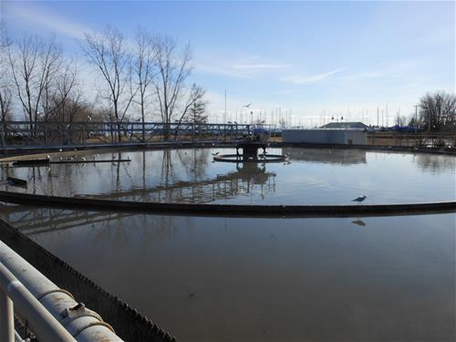
Secondary Clarification

The activated sludge, or “mixed liquor,” is then channeled to two ~1 million gallon circular final clarifying tanks. This is the only part of the plant process where both tanks are utilized. Like the primary clarifier, the velocity is slowed down and the water is calm to allow the solids that were formed in the aeration tank to settle by gravity. This process removes between 10%-15% of the remaining suspended solids. The settled activated sludge is collected in a hopper located in the bottom of the tank. The remaining treated clear water is then diverted to the chlorine contact tank.
Recirculation and Wasting
The activated sludge that is collected in the clarifiers’ hoppers is then either returned to the beginning of the aeration tank via return sludge pumps, or it is wasted back to the primary clarifier where it then settles and mixes with the existing settled solids for dewatering. The quantity of activated sludge that is wasted per hour depends on current plant process requirements. Wasting activated sludge controls the amount of bacteria and activated sludge the aeration tank contains at a given point in time.
Disinfection

Once the water from the secondary (final) clarifiers enters the chlorine contact tank, the velocity is then slowed once again to provide adequate detention time for the added sodium hypochlorite (15% Bleach) to eliminate most of the harmful bacteria and viruses. Before the water enters the Saranac River, sodium thiosulfate is added to remove the remaining sodium hypochlorite that may be remaining in the water. This protects the living organisms in the receiving waters. Disinfection is only required between May 1 and October 31 per the plant’s SPDES Permit.
Phosphorus and Nitrogen
Many nutrients are helpful for the plant’s activated sludge process, but can promote unwanted algae growth in receiving waters. One of these nutrients is phosphorus. Once the activated sludge exits the aeration tank, aluminum sulfate is added at a very small dose to assist with the removal of phosphorus and it also assists with settling of the sludge in the secondary (final) clarifiers. Another helpful nutrient for the plant, but harmful for receiving waters is ammonia /nitrogen. The plant’s natural activated sludge process succeeds at the removal of these nutrients without any added chemicals.
Sludge Dewatering

The excess activated wasted sludge and the sludge which settled initially in the primary clarifier is now pumped from the center hopper of the primary clarifier to 4 belt filter press machines. As the sludge is being pumped, sodium hypochlorite is added to control odors that may be associated with the sludge. Polymer is also added to the incoming sludge to assist with the removal of water. Once the thickened sludge has reached the belt filter presses, it slowly travels through the units and is pressed between very large rollers to remove the excess water. The dried sludge averages around 20% solids by the end of the process. The dewatering process uses a large quantity of wash water to rinse the removed water from the sludge back into the plant’s system. To avoid the usage of the City’s potable water, the plant utilizes it’s own processed final effluent water to assist in this process. The recycled plant effluent water is pumped to the belt filter presses via one of two Return Effluent Pumps. Disposal The resulting dewatered sludge is then dropped into a large trailer which is hauled to either Franklin County Landfill, or a composting facility owned by Casella Organic Waste Management. The plant disposes about 20 to 40 tons of sludge per day to one of the afore mentioned facilities.
Laboratory

The laboratory is located in the Administration Building and this is where process control and state required testing occurs on a variety of different water samples from the plant’s process. Each day, routine tests on suspended solids, settleable solids, pH, chlorine residual, and other tests are performed to ensure that the plant’s process is successful. Tests are run on the plant’s influent wastewater, primary clarifier effluent water, the aeration tank effluent water (mixed liquor), the final effluent water, and also samples from two of the major users: Georgia Pacific and Pactiv’s wastewater. Some of the major tests are outsourced to multiple external laboratories. This is due to the advanced equipment and staff needed to complete these critical state reported tests.
Preventative Maintenance

The maintenance department is the backbone of the plant’s process. Without equipment functioning correctly, the process could fail at some or all of it’s duties. To prevent equipment failure, the plant’s maintenance department has a very in depth and detailed preventative maintenance program. Depending on what the preventative maintenance task is, maintenance personnel perform these tasks daily, weekly, bi-weekly, monthly, semiannually, and annually. These duties include inspections, tests, lubing, oil changes, and basic monitoring of equipment.
Sewer Discharge Information Permits and Local Sewer Use Regulations
If you smell any type of odor which smells like sewage, manure, onions, or any other offensive odor, please use this form or call 518-563-7172 to report it. A staff member will investigate the issue ASAP.
NY Water Environment Association
- Operator jobs
- How to become a wastewater operator
- Wastewater news and events
- Water and wastewater publications
- Public information
- Online education
.